An integrated UHF RFID reader puts the reader electronics and a circularly polarised antenna in one sealed housing, so a single cable and a single bracket cover a vehicle lane, a turnstile or a one-door portal. This page explains the category: the gain classes behind the “built-in 8–9 dB circular” spec line, what Wiegand, RS-485, relay and PoE lines mean for your controller, how IP65 and IP67 differ, how to mount a 2.5–4.3 kg unit, and when a fixed reader with separate antennas is the better buy. Figures come from the published datasheets and standards listed below.
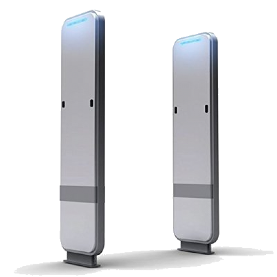
The name describes the construction: an antenna-in-enclosure reader. It runs the same EPCglobal Gen2 / ISO 18000-63 air interface as any UHF RFID reader, with the main antenna already matched, mounted and sealed behind the radome.
Published units pair the RF module with a built-in circular antenna of 8–8.5 dBic (65–80° half-power beam), or 9 dBi circular on one gate unit, in a housing about 290–300 mm square and 71–115 mm deep. The RF path is fixed at the factory: zero coax loss to budget and a matched antenna (VSWR ≤1.4:1 on one gate unit) from day one.
Gate-class datasheets typically add one RP-TNC port and a rugged outdoor class adds three, so the same reader can drive a panel on the opposite kerb or a second lane. Read the external-port line on its own: one flat-panel family rates its external ports at +27 or +30 dBm, against +30 or +33 dBm e.r.p. through the built-in antenna.
Vehicle entry and exit lanes (parking management, gated compounds), personnel gates and turnstiles (access control and attendance), single dock doors, conveyor and workstation cells under a PLC, and any point where one reader serves one zone.
Integrated readers are sold by the antenna inside: gain sets nominal range, beam-width sets zone width. Compare dBic with dBic; the antenna gain guide explains the dBi, dBd, dBic and dBil offsets.
The gate and lane class. One flat-panel family rates its 8 dBic, 80° variant at 5 m nominal at +30 dBm e.r.p. and 7 m at +33 dBm e.r.p.; a 9 dBi gate unit states 0–15 m “according to tag and environment”. Tag and site set the spread, so treat any range line as a ceiling to confirm on site.
The same housing family offers a −2 dBic low-gain antenna rated 1.5 m and a 2 dBi near-field antenna rated 0–20 cm (0–40 cm on the higher-power version), with 2–3 m far-field reach. These suit counters, kiosks and cabinets; USB encoding stations sit on the desktop UHF readers page.
PLC-line units carry an integrated antenna rated for linear (h/v), circular and combined polarisation, with 3–2000 mW transmit power and an 8 m maximum range. Linear suits items that pass in a fixed orientation; circular tolerates tags in any orientation, which is why lane and gate units use it.
Overhead units use a phased array instead of a single fixed antenna: one published class forms 13 beams in 3 sectors to cover about 93 m² from one ceiling point, powered over PoE 802.3af Class 3. They watch open floors and rooms rather than lanes, so they complement the lane units on this page.
| Class | Built-in antenna | Extra RF ports | Transmit power | Host interfaces & GPIO | Supply | Sealing & temperature | Size / weight | Stated range |
|---|---|---|---|---|---|---|---|---|
| Gate / lane | 9 dBi circular, VSWR ≤1.4:1 | 1 × RP-TNC | 0–33 dBm, adjustable | RJ45, RS-232, RS-485, Wiegand; 2 in / 2 out, opto-isolated | 9–30 V DC | IP65, −20 to +70 °C | 290 × 290 × 115 mm, 2.5 kg | 0–15 m (tag and site) |
| Rugged outdoor | 8.5 dBiC circular, 65° | 3 × R-TNC | 33 dBm conducted (ETSI) / 30 dBm, 33 dBm with extended cable (FCC); 33 dBm e.r.p. (ETSI) / 36 dBm EIRP (FCC) | Ethernet; 3 in / 3 out | PoE+ 802.3at (35–57 V) | IP67, −20 to +55 °C | 300 × 300 × 71 mm, 4.26 kg | — |
| Indoor flat panel | 8 dBic, 80° (also −2 dBic, near-field) | External ports at +27 / +30 dBm | +30 or +33 dBm e.r.p. | Optional 4 in / 4 out (24 V in, 50 mA out) | — | IP20, indoor use | — | 5 m / 7 m nominal |
| PLC / industrial | Integrated: linear h/v, circular or combined | 1 external | 3–2000 mW | PROFINET, EtherNet/IP, OPC UA, RS422; 4 in / 4 out | 24 V DC | IP65, −25 to +55 °C | — | Up to 8 m |
| Ceiling gateway | Phased array: 13 beams in 3 sectors | — | — | Ethernet | PoE 802.3af Class 3 | IP50 | 2.70 kg | About 93 m² coverage |
The antenna gain is inside the box, but the regulator still counts it. Read conducted power at the module and the radiated figure it produces; the power-budget guide works the arithmetic.
EN 302 208 V3.4.1 (2023-12) caps the 865–868 MHz band at 2 W e.r.p. (33 dBm) in 200 kHz channels centred at 865.7, 866.3, 866.9 and 867.5 MHz. India’s G.S.R. 853(E) of 10 December 2021 uses the same band, channels and 2 W e.r.p., names EN 302 208 as its reference, and limits continuous transmission on a channel to 4 s with at least 100 ms between transmissions.
47 CFR 15.247 allows 1 W peak conducted output in 902–928 MHz for hopping systems on at least 50 channels, assuming antenna gain of 6 dBi or less; above that, conducted power comes down dB for dB. One rugged unit with an 8.5 dBiC antenna is specified at 30 dBm conducted (33 dBm with extended cable length) and 36 dBm EIRP in the FCC band (33 dBm conducted in its ETSI version), so check how each datasheet states its FCC figure against the gain inside the housing.
EN 302 208 gives, for a circular antenna: conducted power = e.r.p. − gain (dBic) + 5.15 + cable loss, in dB. At the 33 dBm e.r.p. ceiling an 8.5 dBiC built-in antenna with no cable allows 29.65 dBm at the module, a 9 dBic antenna 29.15 dBm. A 0–33 dBm adjustment range lets the installer set exactly that figure.
In the ETSI lower band, EN 302 208 allows any beam-width up to 500 mW e.r.p., at most 180° up to 1 W, and at most 90° from 1 W to 2 W e.r.p. A 65–80° built-in antenna can therefore run at the full 2 W, while a 100° panel on the spare port is held to 1 W.
Rugged lane units publish about −80 dBm typical receive sensitivity, ceiling gateways about −84 dBm. A stated method (ISO/IEC 18046-2:2020, 90% success over at least 100 consecutive tests) makes figures comparable. One test house maps −85 and −75 dBm to roughly 25 m and 12 m in free space, with 6 dB halving range; see the datasheet guide.
Lane and gate work runs through access and parking controllers, so a typical gate-class datasheet lists RJ45, RS-232, RS-485 and Wiegand together, with two opto-isolated inputs and two outputs. The Wiegand and RS-485 guide covers the wiring.
The 26-bit format carries a leading parity bit, an 8-bit facility code (256 codes), a 16-bit ID (65,536 IDs) and a trailing parity bit, sent one way as pulses of about 100 µs at 1 ms intervals over about 90 m of 24 AWG or 150 m of 18 AWG. The reader maps part of the EPC into that frame, so agree the bits and byte order before credentials are encoded.
RS-232 is point-to-point and typically good for about 15 m at 19200 baud. RS-485 is differential multidrop: up to 32 driver/receiver pairs, about 1,200 m at low baud rates and 120 m at 1 Mbps, on 120 Ω terminated twisted pair. For a lane far from the guardhouse, RS-485 or Ethernet carries the link.
Inputs are opto-isolated, 0–24 V on a typical gate unit: a loop detector or photo-eye triggers the read, and outputs drive the barrier controller and a traffic lamp. Match output current to the load: one indoor family rates outputs at 50 mA, a rugged family at 500 mA each (1,500 mA total), with GPIO supply from an external source on PoE+.
IEEE 802.3af delivers about 13 W at the device, 802.3at (PoE+) 25.5 W. Rugged lane units specify PoE+ at 35–57 V and ask for a 30 W static switch port on Cat 6 up to 100 m; gate units take 9–30 V DC. PLC-class units speak PROFINET, EtherNet/IP, OPC UA and RS422, so WIP tracking stations report straight to the line controller.
The sealed housing is the main reason to choose an integrated reader for an outdoor lane, so read the enclosure lines as closely as the RF lines.
Under IEC 60529 first digit 6 means dust-tight. Second digit 5 is water jets from a 6.3 mm nozzle at 12.5 L/min and 30 kPa from 3 m for at least 3 minutes; 7 is 30 minutes of immersion with the lowest point 1 m down. Above IPX6 these are separate tests, so a lane that is hosed down and may flood calls for dual marking such as IP65/IP67.
Outdoor units publish −20 to +70 °C (gate class) and −20/−25 to +55 °C (rugged and PLC classes). Indoor flat panels are IP20 and ceiling gateways IP50, so match the class to the location: IP20 and IP50 units belong indoors, IP65 and IP67 units at the open lane.
Choose a wall or pole bracket whose rated load clears the datasheet mass with margin (2.5 kg for a 290 mm gate unit, 4.26 kg for a 300 mm rugged one) and that tilts in both planes, so the beam can be aimed down at the stop line. Put the bracket and pole hardware on the same quote as the reader.
Tilt the reader toward the windshield or badge line so the beam ends at the stop point. Portal research lists the tools against cross-reads between neighbouring lanes: sensor-gated reads (loop, photo-eye, motion sensor), time-slotting so one reader transmits at a time, RSSI and phase-based motion filtering, and RF-reflective panels. See the stray-read settings guide.
The reader is half of the range equation. Published tag distances below are at 2 W e.r.p. where stated, each footnoted as environment dependent; more on the UHF RFID tags page.
Tamper-evident 92 × 26 × 0.2 mm labels applied inside the glass are rated up to 8 m for both ETSI and FCC tuning; a cryptographic variant up to 10 m (ETSI) / 8 m (FCC). Adhesive shelf life is 1 year at +20 °C / 50% RH, so order labels to consumption.
An ID-1 passive UHF card (86 × 54 × 0.8 mm) is rated up to 9 m with a matched reader. A dual-frequency card adds an HF chip read at about 10 cm, so one credential serves the secure close-range step at the door and the hands-free UHF step at the lane; its UHF distance depends on environment and application, so confirm it with a site test. See RFID cards.
Metal assets need on-metal designs: printable on-metal PET labels read 2.5–4.5 m, plate tags up to 10 m and large flag tags up to 18 m on metal at 2 W e.r.p., all vendor figures for free space or a non-reflective environment. See on-metal RFID tags, and crate and cylinder tracking for a gate-read workflow.
Both are UHF readers on the same air interface. The choice turns on how many read zones one box serves and how far antennas sit from the electronics.
There is one read zone per reader (one lane, turnstile or station); the mounting point is outdoors or exposed; the controller expects Wiegand, RS-485 or relay contacts; and the installer wants one cable and one bracket. The factory-matched antenna puts the full power budget into the zone.
A dock door needs two to four antennas per side, as in most commercial portals surveyed; a wide yard gate needs antennas on both kerbs at height; or many zones share one unit, since four 8-output hubs on a 4-port reader give 32 antennas. See fixed UHF readers, RFID antennas and pallet tracking.
The spare port builds a two-antenna lane from one reader: built-in antenna on the entry side, a 5.5–6 dBic, 100° panel on the exit or far kerb. Budget the external-port rating and cable loss, and in the ETSI lower band keep that panel at or below 1 W e.r.p.
Use the RFQ checklist below so quotes come back comparable. Integrated readers with inbuilt antennas ship from the India RFID Store; export orders are quoted in USD (EXW, FOB, CIF or DDP), with FCC-band (902–928 MHz) or ETSI-band (865–868 MHz) variants configured per order. Handheld readers cover exceptions; RFID hardware lists every category.
Paste these lines into your RFQ and the quotation comes back comparable across suppliers.
Both run the same EPCglobal Gen2 / ISO 18000-63 air interface. An integrated reader carries its main antenna inside a sealed housing (typically 8–8.5 dBic with a 65–80° beam, or 9 dBi circular on one gate unit) plus one to three spare ports, and is sized for one read zone. A fixed reader drives separate antennas from multiple ports, so it serves multi-antenna portals and, through antenna hubs, up to 32 antennas from one unit.
Published figures at 2 W e.r.p.: windshield labels up to 8 m on glass (10 m for an ETSI-tuned cryptographic variant) and ID-1 passive UHF cards up to 9 m with a matched reader. On the reader side, a 9 dBi gate unit states 0–15 m and an 8 dBic flat panel 5–7 m nominal. Set the stop line well inside the tag figure and confirm with a site test, especially for dual-frequency cards, whose UHF distance varies with environment and application.
Yes, wherever the datasheet lists Wiegand output: the reader converts part of the EPC into a 26-bit or longer Wiegand frame and sends it one way over about 90 m of 24 AWG or 150 m of 18 AWG cable. Agree the EPC-to-Wiegand mapping before credentials are encoded, and use RS-485 or Ethernet where the controller supports them, for longer runs and two-way diagnostics.
Gate-class units carry one extra RP-TNC port and rugged units up to three, so a panel on the opposite kerb or a second lane can share the reader. Check the external port’s power rating (one family rates it at +27 or +30 dBm), apply the beam-width rule for your band, and budget the cable loss of the run.
IP65 means dust-tight plus resistance to 6.3 mm water jets; IP67 means dust-tight plus 30 minutes of immersion at 1 m. The water tests are separate, so a lane that is pressure-washed wants the jet rating stated, a flood-prone pit wants IP67, and a unit marked IP65/IP67 covers both. Pair the rating with the operating temperature range; published outdoor units run −20 to +55 °C or −20 to +70 °C.
India’s licence-free UHF RFID rules are G.S.R. 853(E) of 10 December 2021: equipment must be type approved and comply with EN 302 208, and interrogators are limited to 2 W e.r.p. on four 200 kHz channels. The UHF readers Identium supplies are BIS and WPC approved for India’s licence-free UHF band.
Rugged integrated units specify PoE+ (IEEE 802.3at, 25.5 W at the device), and their datasheet asks for a 30 W static switch port over Cat 6 up to 100 m; standard 802.3af delivers about 13 W. Gate-class units with a 24 V / 2.5 A supply take 9–30 V DC instead. State the power you have in the RFQ, and plan an external GPIO supply where the unit runs on PoE+.
Tell us the destination country and the read point — we return the band variant, the antenna plan and a USD quotation with the conformity documents listed.