Panel · Patch · Near-Field · Portal

UHF RFID Antennas
Gain Shapes the Zone, Cable Sets the Budget

A UHF RFID antenna turns the reader’s conducted power into the field that wakes a tag, and its datasheet decides how much of that power is legal, where the read zone falls and how much is lost on the way. This page explains the category line by line: dBi, dBic and dBiL gain; circular versus linear polarisation; half-power beam-width and the beam-width rule tied to 2 W e.r.p.; coax loss per metre; and how many antennas a dock-door portal uses. Every figure comes from a published datasheet, standard or regulation.

UHF RFID Antennas: Gain, Polarisation, Beamwidth & Cable Loss
Beam-width at full 2 W e.r.p.
≤90°
Required above 1 W e.r.p. in the lower band by ETSI EN 302 208 V3.4.1 (2023-12)
dBic vs dBiL, same antenna
2.7–2.9 dB
Gap between circular- and linear-reference gain published for one high-gain patch
Coax loss at 900 MHz
0.13–0.69 dB/m
From 400-grade low-loss coax to RG-58, per the cable makers’ attenuation tables
2 W e.r.p.India’s limit under G.S.R. 853(E), matching the ETSI lower band
6 dBiFCC antenna gain above which conducted power is cut dB-for-dB
3 dBpolarisation mismatch between a linear tag and a circular reader antenna
2–4antennas per side in commercial dock-door portals (2010 portal survey)

What a UHF RFID reader antenna is

The antenna is a passive part: the reader sets the power, the antenna shapes and points it. Three construction classes cover most installations, each specified in its own terms.

radio

Far-field panels

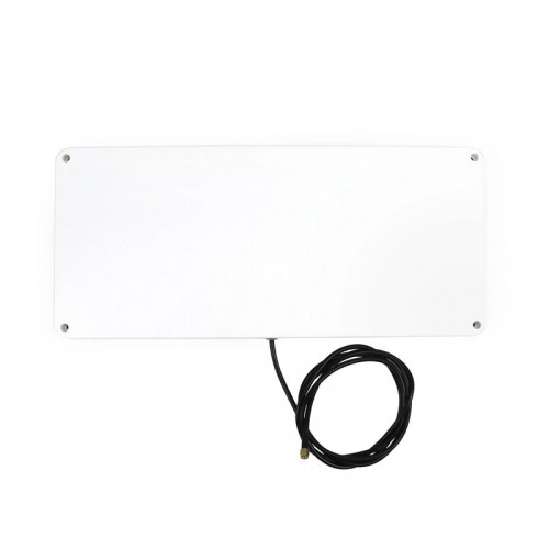
The workhorse class is a flat, circularly polarised panel, 250–260 mm square, 14–34 mm deep and 0.75–1.04 kg in the datasheets reviewed, with 8–9 dBic gain and a 68–70° beam. They face dock doors, conveyors and vehicle lanes from any fixed reader port.

minimize

Near-field antennas

Near-field antennas couple magnetically to tags at a counter or encoding desk. One class is rated for 7.5 cm or less, with a deliberately weak −20 dBi far-field gain to suppress stray reads; a 30 cm table-top disc reads up to 15 cm with a pure near-field tag and up to 40 cm with a transitional tag.

columns

Portal assemblies

A dock-door or transition portal is a set of antennas either side of an opening, usually two to four per side in commercial designs. Where one antenna is enough, an integrated reader carries it inside the housing and removes the coax run.

plug

The reader sets the power

Antennas carry a maximum input rating (2–3 W absolute for the near-field designs, 6–10 W for the far-field panels reviewed) at or above the 30–33 dBm a fixed-reader port supplies. What reaches the air is reader power minus cable loss plus antenna gain, and that sum is what regulators limit.

Gain units: dBi, dBd, dBic and dBiL

Gain is the most misread datasheet line: four reference units are in common use, and a bare “dBi” can stand for either of two. The gain-units guide works every conversion.

scale

dBi and dBd differ by 2.15 dB

dBi is gain over an isotropic radiator; dBd is gain over a half-wave dipole, which itself has about 1.64× (2.15 dB) gain over isotropic, so G(dBi) ≈ G(dBd) + 2.15 dB. India and Europe set limits in e.r.p. (dipole reference); the FCC sets its gain threshold in dBi.

refresh-cw

dBic versus dBiL on one antenna

A circularly polarised antenna can be rated against a circular reference (dBic) or a linear one (dBiL). One high-gain patch datasheet publishes both: 10.9 dBic typical against 8.2 dBiL in its EU version, and 11.4 dBic against 8.5 dBiL in its US version, a gap of 2.7–2.9 dB. Ask which reference a bare “dBi” figure uses.

compass

Gain and beam-width move together

Higher gain means a narrower beam. Across four published circular far-field antennas: 3.2–3.6 dBic at 100° × 100°, 8.3 dBic at 68°, 9 dBic at 70° azimuth and 10.9–11.5 dBic at 40° × 40°. Range grows as the zone narrows, so a wide room suits a wide beam and a conveyor suits a focused one.

ruler

Read gain at band centre, per region

Datasheets quote gain at the centre of each regional version, and versions differ: one wide-beam patch is 3.2 dBic typical in its EU build and 3.4 dBic in its US build. Order the version tuned for the destination band.

Antenna classGainHalf-power beamVSWREnclosureTypical placement
Wide-beam patch3.2–3.6 dBic (0.8–1.1 dBiL)100° × 100°<1.5:1 typicalIP62, or IP67 in rugged enclosureSmart shelves, tables, display panels
Slim outdoor panel8.3 dBic68° both planes<1.3IP67, ABS radomeDoors, lanes, outdoor walls
10-inch portal panel9 dBic70° azimuth1.3:1 maxIP54, polycarbonate radomeDock doors, distribution centres, conveyors
Pencil-beam patch10.9–11.5 dBic (8.2–8.5 dBiL)40° × 40°<1.5:1 typicalIP60Fitting rooms, vehicle and people tracking
Near-field−20 dBi to 6 dBi max far-field, by designSpecified as a read zone: up to 7.5 cm, or 15–40 cm by tag type1.8 typical (planar type)IP41–IP53, indoorCounters, encoding desks, point of sale

Circular or linear polarisation

Most commercial UHF tags are linear, dipole-like structures that read best when aligned with the reader’s field, so polarisation is a decision about how predictable tag orientation is on site.

rotate-cw

Circular reads any orientation, at a 3 dB cost

A circularly polarised antenna splits its power across two planes, so it reads tags at any rotation but loses about 3 dB against a linear tag, as peer-reviewed literature states. It is the default for mixed pallets, totes and people, wherever tag angle is unknown.

move-horizontal

Linear reaches farther when orientation is fixed

A linear antenna of the same gain keeps its power in one plane and reads farther, provided tags arrive aligned with it. Confirm orientation on the line first: one inlay datasheet shows range falling to 12% of maximum when the inlay is turned perpendicular to the reader antenna.

target

Axial ratio: how circular is circular

Axial ratio measures how evenly a circular antenna radiates in both planes; 0 dB is ideal. It widens toward the beam edge: one wide-beam patch is 0.9 dB at boresight but up to 3.8 dB at its 3 dB beam edge (EU version), while a high-gain patch holds 0.1–0.4 dB across its beam. Portal-class panels publish 1 dB or below.

layers

Hand and dual-linear options

Circular panels come in left-hand (LHCP) and right-hand (RHCP) versions; one 9 dBic panel datasheet lists both. One commercial portal described in a 2010 university survey uses dual-linear phased-array antennas that alternate vertical and horizontal polarisation to cover both tag orientations.

Legal power: e.r.p., EIRP and the beam-width rule

Regulators limit radiated power, so antenna gain and cable loss decide how much conducted power the reader may supply. The power-budget guide works full examples.

flag

India and the ETSI lower band: 2 W e.r.p.

India’s G.S.R. 853(E) of 10 December 2021 sets 865–868 MHz at 2 W e.r.p., channels of 200 kHz or less, on four channels centred at 865.7, 866.3, 866.9 and 867.5 MHz, and names EN 302 208 as its reference standard. EN 302 208 V3.4.1 (2023-12) sets the same envelope, 2 W (33 dBm) e.r.p., for Europe’s lower band.

crosshair

Beam-width is tied to power

EN 302 208 narrows the permitted antenna beam as e.r.p. rises. In the lower band: any beam up to 500 mW e.r.p., 180° or less above 500 mW to 1 W, and 90° or less above 1 W to 2 W. A 68–70° panel therefore qualifies for the full 2 W e.r.p., while a 100° wide-beam patch runs at up to 1 W e.r.p., as its own datasheet notes.

globe

Europe’s upper band and the FCC band

EN 302 208 also opens 915–921 MHz in Europe at up to 4 W e.r.p. on 400 kHz channels at 916.3, 917.5 and 918.7 MHz, with 90° or less required above 2 W. In the US, 47 CFR 15.247 allows 1 W peak conducted output for frequency-hopping systems using at least 50 hopping channels in 902–928 MHz, and requires a dB-for-dB cut for antenna gain above 6 dBi, so 1 W into 6 dBi gives 4 W (36 dBm) EIRP.

calculator

The ETSI conversion, worked

EN 302 208 gives the conducted power for a circular antenna as: e.r.p. limit − antenna gain (dBic) + 5.15 + total cable loss, all in dB or dBm. For 2 W (33 dBm) e.r.p., a 9 dBic panel and 1.5 dB of cable: 33 − 9 + 5.15 + 1.5 = 30.65 dBm at the reader port, within the PoE+ ceilings of current fixed readers.

zap

e.r.p. versus EIRP

EIRP is referenced to an isotropic radiator and e.r.p. to a dipole, so EIRP ≈ e.r.p. + 2.15 dB. A 2 W (33 dBm) e.r.p. limit is about 35.15 dBm (3.28 W) EIRP; the FCC’s 4 W EIRP is about 33.85 dBm (2.43 W) e.r.p. The 5.15 dB term in the ETSI formula equals that 2.15 dB offset plus 3 dB.

Coax loss per metre, connectors and routing

Every decibel lost in the cable comes off the radiated power, and under an e.r.p. limit the reader must make it up. The 900 MHz column of cable datasheets is the closest published point to 866 and 915 MHz.

cable

Loss per metre at 900 MHz

From the cable makers’ attenuation tables: 400-grade low-loss coax (10.3 mm) about 0.13 dB/m; 240-grade (6.1 mm) about 0.25 dB/m; 195-grade (4.95 mm) about 0.36 dB/m; RG-213 (10.3 mm) about 0.25 dB/m; RG-58 (4.9 mm) about 0.69 dB/m. RG-213 and 400-grade share a diameter yet differ about twofold in loss.

bar-chart

Ten metres, four answers

Over a 10 m run those figures become about 1.3 dB (400-grade), 2.5 dB (240-grade or RG-213), 3.6 dB (195-grade) and 6.9 dB (RG-58). In the worked example, swapping 6 m of 240-grade for RG-58 lifts the required reader output from 30.65 to about 33.3 dBm, above the 30 dBm (PoE) and 31.5–33 dBm (PoE+) ceilings one current fixed reader publishes.

plug

Connectors and leads

Panels ship with a coax pigtail ending in an RP-TNC male, or with an SMA female or MCX socket on the body. Vendor lead cables run 2 to 8 m with SMA-to-RP-TNC ends, in 240 and 400 grades, plus 195 grade at 2 m, and one maker specifies finger-tight assembly for SMA.

corner-down-right

Bend radius and routing

Lower-loss cable is thicker and stiffer: 400-grade specifies a 25.4 mm minimum bend radius for installation and 101.6 mm for repeated bending, 240-grade 0.75 in and 2.5 in. Place the reader close to its antennas, route runs gently, and use the lowest-loss grade the bends allow.

Portals, mounting and environment

Dock doors are where antenna count, placement and power interact most. The portal design worksheet and the missed-reads and stray-reads guide go deeper.

layout-grid

Two to four antennas a side

A 2010 University of Ottawa survey of commercial portals found the common layout is two free-standing portals facing each other across the door, each housing two to four antennas. Count reader ports from that layout: two to four antennas per side means four to eight per door, fed from one or more fixed readers.

truck

One published dock-door layout

For a 30 × 20 ft (about 9 × 6 m) doorway, one installation guide uses a 4-port reader with one antenna low on each side of the door and two above it pointing down, at 30 dBm reader power, with tags chosen for at least about 30 ft of read range so the field penetrates pallet layers. Site-test it before fixing brackets.

filter

Controlling cross-reads between doors

The survey names read accuracy and cross-reading at adjacent doors as the chronic portal problems. Remedies: time-slotting readers so one door transmits at a time, photo-eyes or motion sensors that gate reading, RSSI-and-phase motion detection, stray-tag filtering on triggers, and RF-reflective mesh panels that contain the field.

wrench

Mounting and brackets

Panels mount to a wall or mast bracket through studs or bolt holes on the back plate. Take the hole pattern from the supplier’s drawing, choose an articulating bracket so the beam can be aimed during the site test, and match the bracket’s weight rating to the panel (0.75–1.04 kg in the datasheets reviewed).

droplets

IP rating and temperature together

Published ratings run from IP53 (planar near-field, 0 to +50 °C) and IP54 (polycarbonate panel, −25 to +70 °C) through IP60 (thin high-gain patch) and IP62 or IP67 by enclosure (wide-beam patch, −20 to +80 °C), to IP67 for permanent outdoor use (ABS slim panel, −20 to +55 °C). Quote IP, temperature and radome together.

Choosing an antenna by application

Start from the read zone, then pick the class whose gain, beam and polarisation produce it within the legal power. Pair it with the right tag: labels and inlays for cartons and apparel, on-metal tags for steel assets.

warehouse

Dock doors and pallets

Circular 8–9 dBic panels with a beam of 90° or less, two to four per side, keep the full 2 W e.r.p. available in ETSI-band and Indian deployments. Pallet tracking and warehouse management rely on portals of this kind at receiving and dispatch.

package

Conveyors and sortation

Identically labelled cartons suit a linear antenna; mixed orientation calls for circular. A narrower, higher-gain beam keeps the zone on the belt. Logistics and supply chain shows where conveyor reads fit in a distribution flow.

shopping-bag

Shelves, tables and fitting rooms

Wide-beam patches of about 3 dBic and 100° cover shelf and table tops at short range, within the 1 W e.r.p. that applies to their beam in the ETSI lower band; 40° pencil-beam patches suit fitting rooms. Apparel retail draws on both classes.

scan-line

Counters, encoding desks and item checks

Near-field antennas keep reads to the item on the counter (up to 7.5 cm for one design, 15–40 cm by tag for another) at point of sale, pharmacy, library and jewellery desks. They pair with a desktop reader or one port of a fixed reader.

car

Vehicle lanes and outdoor gates

IP67 slim panels rated for permanent outdoor use, or an integrated reader with its antenna sealed in, cover parking and gate lanes. Where a cabinet reader feeds a pole-mounted panel, keep the coax short and specify 400-grade for longer runs.

shopping-cart

Buying and specifying

Identium designs and manufactures UHF RFID antennas and gates in-house, supports OEM/ODM builds and quotes in USD on EXW, FOB, CIF or DDP terms. Stock antennas are on the India RFID Store. Work the read-range example first; see also UHF readers, handhelds and all RFID hardware.

What to Put in the Enquiry

Paste these lines into your RFQ and the quotation comes back comparable across suppliers.

  1. UHF RFID reader antenna, far-field panel; destination band stated (ETSI lower band 865–868 MHz, FCC 902–928 MHz or other) and the matching regional version supplied.
  2. Gain stated in dBic and dBiL (or dBi with the reference named), typical and maximum, measured at band centre.
  3. Half-power (3 dB) beam-width in azimuth and elevation; for 2 W e.r.p. in the ETSI lower band or India, beam-width 90° or less per EN 302 208 V3.4.1.
  4. Polarisation: circular (LHCP or RHCP) or linear (vertical or horizontal); axial ratio at boresight and at the 3 dB beam edge, typical and maximum.
  5. Electrical: 50 Ω; VSWR 1.5:1 or better across the band; front-to-back ratio 15 dB or better; maximum input power in W; DC-grounded radiator; antenna-detection resistance where the reader uses it.
  6. Connector RP-TNC or SMA with gender stated; pigtail or body-mount; lead cable grade and length with loss at 900 MHz in dB on the quotation.
  7. Power budget from the supplier: reader conducted power that meets the legal limit for the quoted gain and cable loss (ETSI: e.r.p. − dBic + 5.15 + cable loss; FCC: 1 W conducted, reduced above 6 dBi).
  8. Environment: IP rating per IEC 60529 with test condition, radome material, operating temperature range and UV resistance for outdoor sites.
  9. Mechanics: dimensions, weight, dimensioned drawing with stud or hole pattern, articulating wall or mast bracket and its weight rating.
  10. Near-field or portal items: read zone in cm with the reference tag; antennas per side, mounting heights, cross-read controls and a site test with our own pallets and tags before volume order.

UHF RFID Antennas, Answered

What is the difference between dBi and dBic on an RFID antenna datasheet?

dBi is gain relative to an isotropic radiator; dBic is the same reference measured with circular polarisation, and dBiL with linear. For one circular antenna the circular figure reads higher: a published high-gain patch lists 10.9 dBic against 8.2 dBiL, a 2.7–2.9 dB gap across its versions. Compare antennas in the same unit, and confirm which reference a bare “dBi” uses before running a power budget.

Should I choose a circular or a linear polarised antenna?

Choose circular when tag orientation varies (mixed pallets, totes, people): it reads at any rotation at a cost of about 3 dB. Choose linear when every tag passes in the same orientation, such as identical cartons on a conveyor, and take that 3 dB back as range. Test with real items first, since one inlay datasheet shows range falling to 12% of maximum with the inlay perpendicular to the antenna.

How many antennas does a dock-door portal need?

Most commercial portals place two to four antennas on each side of the door, facing each other. One published layout for a 30 × 20 ft door runs four antennas from a single 4-port reader: one low on each side and two overhead, at 30 dBm reader power. Size the final count from a site test with your own pallets, and manage cross-reads between adjacent doors with time-slotting, photo-eye triggers or RF-reflective mesh.

What is the maximum legal radiated power for a UHF RFID antenna?

In India (G.S.R. 853(E), 865–868 MHz) and the ETSI lower band, 2 W e.r.p. on four 200 kHz channels; EN 302 208, the reference standard India’s rules name, requires antennas of 90° beam-width or narrower above 1 W e.r.p. In the US (47 CFR 15.247, 902–928 MHz), 1 W peak conducted for frequency-hopping systems with at least 50 hopping channels, reduced dB-for-dB for antenna gain above 6 dBi, which works out to 4 W EIRP. Europe’s 915–921 MHz upper band allows more on wider channels.

How much signal does antenna cable lose?

At 900 MHz, published attenuation is about 0.13 dB per metre for 400-grade low-loss coax, 0.25 dB/m for 240-grade or RG-213, 0.36 dB/m for 195-grade and 0.69 dB/m for RG-58. A 10 m run therefore costs about 1.3 dB in 400-grade and 6.9 dB in RG-58. Under an e.r.p. limit every decibel lost has to come from extra reader output, so keep runs short and name the grade on the quotation.

Can a wide-beam antenna run at full power?

Under EN 302 208, the full 2 W e.r.p. in the lower band is reserved for antennas with a half-power beam of 90° or less; a 100° wide-beam patch runs at up to 1 W e.r.p., which suits its short-range shelf and table work. For a portal at 2 W e.r.p., choose 68–70° class panels. In the FCC band the rule works through gain instead, with conducted power reduced above 6 dBi.

How far will a UHF RFID antenna read a tag?

Range is set by the whole link: reader power and sensitivity, cable loss, antenna gain and, above all, the tag and the surface it sits on. Tag datasheets quote theoretical ranges, for example 11 m in free air and 7 m on glass for a general-purpose inlay in the ETSI band, and up to 10 m on metal at 2 W e.r.p. for a plate-class on-metal tag. Run the read-range worked example, then confirm with a site survey.
Specify it once, quote it anywhere.

Tell us the destination country and the read point — we return the band variant, the antenna plan and a USD quotation with the conformity documents listed.