An RFID label is an inlay, a chip and an aluminium antenna on a PET film, with a face, an adhesive and a liner built around it, and every layer shows up somewhere on the datasheet. This page reads that datasheet line by line: dry and wet inlays against paper and PET labels, chip memory and sensitivity, antenna size against read range, EPC, TID and user-memory encoding, the placement a printer-encoder needs, and the ARC and TIPP specs retailers use for source tagging. Standard rolls are listed at India RFID Store.
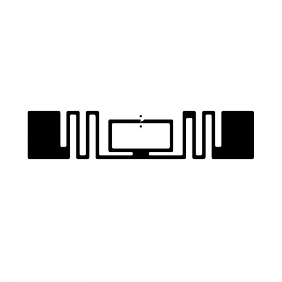
Four terms describe the build, and each one changes how the roll is handled, printed and applied. Ask for the build by name, then check its layers.
Chip, antenna and substrate with a clear face and no adhesive: the raw material converters build into labels, tags and cards. One maker’s build is a 10 µm aluminium antenna on 50 µm PET. One 44 × 28 mm design ships 18,000 per reel as dry inlays.
The same inlay with adhesive on a release liner and a clear PET face, for peel-and-stick tagging where the tag carries no print of its own. The 44 × 28 mm design above ships 15,000 per reel wet. Specify the adhesive and the surface it goes on, exactly as for a printed label.
A label adds a printable paper or white plastic face, so one pass through a printer-encoder yields barcode, text and an encoded chip. A typical converted paper build is 2.6 mil topcoated paper, 0.6 mil acrylic adhesive and a 2.4 mil kraft liner, 5.6 mil ±10% in total, printable at up to 14 in/s and meeting FDA 175.105 for indirect food contact.
Current inlays are commonly rated −40 to +85 °C, while the paper build above is specified for −18 to +82 °C service, application at −4 °C or warmer, and indoor use, so the face and adhesive set the envelope. Ask for three temperatures: continuous operating range, peak exposure, and any process profile such as a wash or sterilisation cycle.
On-metal labels are 0.9–1.2 mm white PET with a backing made for metal, reading 2.5–4.5 m on metal at 2 W reader ERP (see on-metal tags). Windshield labels are 92 × 26 × 0.2 mm, non-transferable and tamper-evident, with theoretical range up to 8 m on glass for vehicle parking and access. Jewellery loop labels wrap a 35 mm tail around a ring shank, bracelet or necklace.
Inlays are named by antenna size; the die-cut, or finished size, is a few millimetres larger. Chip, surface, orientation and band tuning then shape the read range.
Published inlays cluster into a mini class at 42 × 16 mm (die-cut 45 × 18 mm), item-level at 44 × 28 mm (47 × 31 mm), general purpose at 50 × 30 mm (53 × 33 mm) and the “belt” or strap class at 70 × 14.5 mm (73 × 17 mm). Quote both the antenna and the die-cut size in the order.
The mini class is positioned for difficult-to-tag, low-detuning items such as cardboard and plastic packaging, the everyday stock of RFID inventory management. On retail programmes the category’s ARC Spec and its approved list set the candidate inlays first; range testing on the real item then picks between them.
Theoretical range is typically computed from measured tag sensitivity at 35 dBm EIRP, equal to 33 dBm ERP or 2 W ERP: the ETSI lower-band limit, also set by India’s 865–868 MHz rules under G.S.R. 853(E). Under the FCC 4 W EIRP limit, add about 11%. One maker draws its graphs at 29 dBm reader power and −70 dBm antenna sensitivity. See our read-range worked example.
One 70 × 14.5 mm inlay with a −23 dBm chip lists theoretical range in free air of 11 m (ETSI) and 15 m (FCC), then 13 / 11 m on cardboard, 12 / 16 m on PVC, 14 / 5 m on rubber and 7 / 2 m on glass. The surface behind the label shifts each band differently.
The same datasheet shows range falling to 12% of maximum when the inlay sits perpendicular to the reader antenna, so place labels to face the read zone. Order tuning by destination: ETSI-tuned for Europe and India (865–868 MHz), FCC-tuned for 902–928 MHz, or global for mixed supply chains; see RFID frequency bands by country.
The chip fixes memory, sensitivity and write endurance before the antenna is designed, and retail approved lists name each inlay with its chip. Impinj, NXP and Alien chip families appear below because buyers specify them.
Retail parts carry 96–128 EPC bits and 0–32 user bits, enough for a serialised item number. Extended-memory parts stretch to a 496-bit EPC or 384–752 user bits for batch, service or maintenance data; on one family that costs 0.5 dB, with the M780 and M781 reading at −23.5 dBm against −24 dBm.
Retail-class chips read at −23 to −24 dBm and write at −18 to −22 dBm; the more negative the figure, the less energy the chip needs. Writing needs more signal than reading, which is why printer-encoders calibrate read and write power for each inlay type.
Write endurance and data retention separate the lowest-cost parts from industrial ones: 10,000 cycles and 10 years on the cheapest retail chips against 100,000 cycles, and 20 years where stated, on the industrial-class parts in the table. Choose the higher figure wherever labels are rewritten in service, such as returnable containers or reissued items.
Where a serial must resist cloning, cryptographic chips add a secret key. One family member adds authentication at the same −24 dBm; the AES-128 authentication part reads at −19 dBm and writes at −11 dBm, and its maker lists automatic vehicle identification, access management, brand protection and supply chain management among its uses.
| Chip | EPC bits | User bits | Read / write sensitivity | Write cycles / retention | Note |
|---|---|---|---|---|---|
| Impinj M730 | 128 | 0 | −24 / −21 dBm | 10,000 / 10 yr | Retail apparel lists |
| Impinj M750 | 96 | 32 | −24 / −21 dBm | 10,000 / 10 yr | Small user bank |
| Impinj M770 | 128 | 32 | −24 dBm read | 100,000 / 20 yr | Industrial endurance |
| Impinj M775 | 128 | 32 | −24 dBm read | 100,000 / 20 yr | Cryptographic authentication |
| Impinj M780 | 496 | 128 | −23.5 dBm read | 100,000 / 20 yr | Long EPC |
| Impinj M781 | 128 | 512 | −23.5 dBm read | 100,000 / 20 yr | Large user bank |
| NXP UCODE 8 / 8m | 128 / 96 | 0 / 32 | −23 / −18 dBm | 100,000 minimum | 96-bit TID, 48-bit serial |
| NXP UCODE 9 | 96 | 0 | −24 / −22 dBm | 100,000 / 20 yr | Self-adjust across materials |
| NXP UCODE 9xm | 128 / 256 / 496 | 752 / 624 / 384 | −24 / −22 dBm | 100,000 / 20 yr | Configurable memory split |
| NXP UCODE DNA | up to 224 | up to 3,072 | −19 / −11 dBm | 100,000 / 20 yr | AES-128 cryptographic authentication |
| Alien Higgs-9 | 96 | 688 | — | — | User bank relocatable to EPC |
M730/M750 write figures from one inlay datasheet; Higgs-9 memory from its 2019 launch release.
Every Gen2 label carries four memory banks. The RFQ should say what goes in each and who writes it: inlay maker, converter or printer-encoder.
Reserved memory holds the 32-bit kill and access passwords; the EPC bank holds the item identifier; the TID bank opens with class identifier E2h, a 9-bit mask-designer ID and a 12-bit model number; optional User memory carries extra data encoded with GS1 Application Identifiers. See our Gen2 memory guide.
Encode the EPC to the current release of the GS1 EPC Tag Data Standard and name both the release and the scheme in the order, for example SGTIN-96 for serialised trade items; see our SGTIN-96 walkthrough. A serialised identifier is also the key a digital product passport record hangs from.
Many chips carry a factory-locked 96-bit TID with a 48-bit unique serial, so every inlay arrives with an identity fixed at the chip factory. Multi-vendor chip-based serialization (MCS) is now listed even on desktop printer-encoders.
Industrial printer-encoders write expanded EPC and user memory, read the 96-bit TID, and set access and kill passwords and lock states in the same pass. Decide the lock policy before ordering: which banks are locked or permalocked, who holds the access password, and whether user memory is written at source or in the field.
Where the inlay sits on the liner decides whether a roll encodes cleanly. Printer makers publish placement rules, and converters build rolls to them.
Media is defined by inlay centre ‘a’ (left liner edge to antenna centre), inlay position ‘x’ (label start to antenna leading edge) and inlay pitch ‘y’ (leading edge to next leading edge), with ‘a’ and ‘x’ typically held to ±3 mm. The reference is the antenna rather than the chip; pitch can differ from label length plus gap, with about 16 mm the usual minimum.
Desktop encoders usually have one coupler antenna in the centre of the media path, behind the platen roller. Centre the inlay across the web within ±2 mm and, on labels longer than about 1 in, place it about 10–15 mm from the leading edge; an ‘x’ of at least 10 mm keeps backfeed to a minimum.
Some industrial encoders use a 20-element antenna array, so inlays centred 0.5, 1, 1.5 or 2 in from the left liner edge (±3 mm) encode without special placement. On labels longer than about 1 in, keep the inlay at least 15 mm from the leading edge; labels under about 1 in pitch may need a short backfeed.
RFID calibration steps the label through 1 mm at a time, reads the chip TID and stores the best programming position, read and write power and antenna element; it can take up to 5 minutes. Each label is encoded, verified and printed; a failed tag is printed VOID and its data retried on the next label, three times by default, configurable from 1 to 10.
Foil or metal-based media needs inlays designed for it. One industrial printer lists on-metal tag thickness up to 1.2 mm, and another offers a field-installable on-metal RFID kit. Media runs 0.06–0.19 mm thick on desktop paths and 0.058–0.25 mm on industrial ones; see RFID printers.
Retail programmes buy labels against a performance spec rather than a part number, and suppliers tag at source to the retailer’s playbook. Our UHF tender specification template turns this vocabulary into clauses.
Auburn University’s RFID Lab founded ARC in 2009 as a common language for passive UHF inlay requirements. End users define a Spec from use case, packaging, environment and RFID infrastructure; the lab benchmarks inlays against it; suppliers then choose from the item’s approved list in the retailer’s playbook.
One major US retailer maps apparel, headwear, footwear, accessories, watches and jewellery to Spec R, most boxed home goods such as cookware and small appliances to Spec Y2, and ceramic or glass candles to Spec C2. See RFID apparel and fashion retail and, for loop labels on rings and chains, RFID jewellery management.
An inlay’s approvals come from the lab’s benchmarking against each Spec, and datasheets list the letters passed, for example F, G, H, I, K, N, O, Q, R, Y and B1 for one 70 × 14.5 mm inlay. Ask for the letters with the inlay part number and chip, and match them to the Spec your retailer names.
GS1’s Tagged-Item Performance Protocol grades the finished item rather than the bare inlay: S for a single item or M for stacks of 2 or 11, a two-digit level in multiples of five, a family letter (B, V or D) and an optional FCC or ETSI range. Grades listed in October 2016 included S05V, S15B, S20B and M20D, measured from −25 dBm.
Specify delivery format with reel data: one 44 × 28 mm inlay runs at 34 mm pitch on a 50 mm web, a 42 × 16 mm design at 20 mm on a 48 mm web, both on 76 mm cores. Ask for minimum yield (one maker states 99% dry, 98% wet and paper-face) and test on the real item; inlay makers publish indicative curves and ask for end-use testing.
Paste these lines into your RFQ and the quotation comes back comparable across suppliers.
A dry inlay is chip, antenna and substrate with a clear face and no adhesive; a wet inlay adds adhesive on a release liner; a label adds a printable paper or white plastic face. Dry inlays suit converters, wet inlays suit peel-and-stick tagging without print, and labels suit printing barcode and text while encoding the chip in one pass. Hard tags put the inlay in an encasement; see UHF RFID tags.
Start from the item and the buyer’s approved list: on retail programmes the ARC Spec for the category, such as Spec R for apparel, sets which inlays qualify. The 42 × 16 mm mini class is positioned for cardboard and plastic packaging. Then test the shortlist on the real item: one inlay falls from 11 m in free air to 7 m on glass (ETSI), and to 12% of maximum when perpendicular to the antenna.
A serialised retail item needs a 96- or 128-bit EPC, which is what the retail-class chips on approved lists carry, often with no user memory. Choose 32 to 3,072 user bits only when data must travel with the item, such as batch or service records. The large-memory parts read at −23.5 to −24 dBm, close to retail parts, while the AES-authentication part reads at −19 dBm.
Check three things against the printer maker’s media guide: inlay placement (‘a’ and ‘x’ within about ±3 mm), pitch at or above the roughly 16 mm minimum, and media thickness within the printer’s range. Run RFID calibration with the actual roll and watch the void counter; when every label voids, the maker’s troubleshooting table points first to calibration for that media. See RFID printers.
Order ETSI-tuned inlays for Europe and for India, where the licence-free UHF band is 865–868 MHz at 2 W e.r.p. under G.S.R. 853(E) of 10 December 2021, and FCC-tuned inlays for 902–928 MHz markets. Global tunings serve mixed supply chains, and region-specific versions can read farther: one small on-metal tag lists 5 m (EU) global-tuned against 7 m for its EU-only version.
Yes. Identium supplies labels and inlays alongside the readers and software it builds in-house, takes OEM/ODM orders, exports worldwide and quotes in USD on EXW, FOB, CIF or DDP terms. Paste the RFQ checklist above into your enquiry; standard rolls are listed at India RFID Store.
Tell us the destination country and the read point — we return the band variant, the antenna plan and a USD quotation with the conformity documents listed.