RAIN RFID Regional Reader Profiles Decoded: IN8A, EU8A, US9A and the Rest
A RAIN RFID reader ships with a region profile: a short code — IN8A, EU8A, US9A — that sets six radio parameters in one move. Set it to the wrong region and you have a reader on a channel plan the destination never allocated, or one throwing away half its tag-reply speed for nothing.
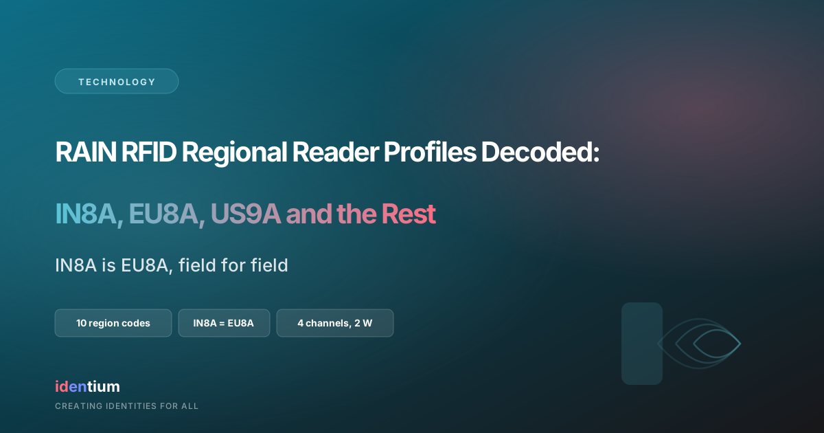
The codes are defined by the RAIN Alliance, in a PDF. This page reproduces that definition as a page, every figure carried back to the edition and clause it came from, alongside the ETSI and Indian source text the lower-band profiles rest on. One fact belongs at the top, because competitor pages still publish the opposite: IN8A and EU8A are identical in every field. India runs the same air-interface profile as Europe’s lower band.
Where the region codes are published
Three documents answer “which region code does this reader need?” All three are files.
- The RAIN Alliance System Design Guidelines define the codes. Version 2.0, dated September 2023 on its own title page, is a 24-page PDF. Table 1 is the authoritative profile grid, 24 pages into a download, with no address of its own and its channel plans drawn as images. Readable as a document. This page adds what a document leaves out: a row you can quote and link to directly.
- The GS1 allocation reference those guidelines point readers to — uhf_regulations.pdf on gs1.org, cited in the guidelines as “Additional information is also provided by GS1” — returned HTTP 403 to a plain request when we fetched it on 25 September 2026.
- ETSI EN 302 208, the standard both the European and Indian lower-band profiles rest on, runs to 71 pages in its current V3.4.1 edition. The four channel centre frequencies occupy one small table on page 14.
An HTML page takes a deep link to a single row, pastes into an answer, and turns up on the one phrase a buyer searches. That is why this table lives as a page: an anchor per region code, every figure carrying its source edition and clause, open on the page for anyone who wants to check it. Dates here are the ones printed on each document’s face rather than the year in its URL — the V2 guidelines sit at a 2024 upload path and read “V.2.0 – September 2023” on the cover.
What each column actually sets
Table 2 of the guidelines defines six of the column headings; the seventh, REMARK, carries the power ceiling as printed in Table 1. Below is each one, plus what changes on site when a value belongs to another region.
- Code. ISO 3166-1 alpha-2 country code, a digit for the band family (8 for 800 MHz, 9 for 900 MHz), then a letter for the plan variant. IN8A reads: India, 800 MHz family, plan A.
- TX-BW (kHz). Maximum transmit bandwidth the reader may occupy. Bandwidth is defined differently region to region, so this is a setting; the measured figure regulators test against lives in the test report.
- TX-SP (kHz). Spacing between transmit channels — 600 kHz against a 200 kHz channel in the lower band, three times the bandwidth. That leaves two empty 200 kHz slots between every pair of reader carriers, and those gaps are where the tags answer. Set 200 kHz spacing on a lower-band reader and you have parked carriers in the reply slots.
- BLF (kHz). Backscatter link frequency as defined in GS1 EPC Gen2 and ISO/IEC 18000-63: the rate the tag answers at. 320 kHz in the lower band, 640 kHz in Europe’s upper band, 256 kHz in the US and China profiles.
- DRM. Whether dense reader mode applies and which M value — subcarrier cycles per symbol — to use. Every profile says yes, M=4.
- CH-USE. Channel-access discipline: AFA (adaptive frequency agile), FHSS (frequency hopping), CS (carrier sense, or listen-before-talk) or NCS (non-carrier-sense). Europe and India take AFA; the US, China and KR9A take FHSS; JP9B, JP9C and KR9B take carrier sense; JP9A is non-carrier-sense under licence. This column varies most, and is the one firmware most often has to change.
- Remark. The power ceiling that goes with the profile, and whether it is e.r.p., e.i.r.p., or conducted power plus a reference antenna gain. Reading “4 W” without reading which of the three has cost projects a retest.
The profile table
Reproduced from Table 1 of the RAIN RFID System Design Guidelines, V.2.0, September 2023. Ten codes, one anchor per row.
| Code | TX-BW / kHz | TX-SP / kHz | BLF / kHz | DRM | CH-USE | Remark |
|---|---|---|---|---|---|---|
| EU8A | 200 | 600 | 320 | Yes, M=4 | AFA | Max. 2 W erp |
| EU9B | 400 | 1200 | 640 | Yes, M=4 | AFA | Max. 4 W erp |
| US9A | 250 (500 channel width) | 500 | 256 | Yes, M=4 | FHSS | Max. 4 W eirp |
| CN9A | 250 | 500 (250 would be possible) | 256 | Yes, M=4 | FHSS | Max. 4 W eirp |
| JP9A | 200 | 1200 | 320 | Yes, M=4 | NCS | Max. 1 W conducted + 6 dBi antenna, licensed |
| JP9B | 200 (200–600 allowed, not supported by this code) | 1200 / 200 | 320 | Yes, M=4 | CS | Max. 1 W conducted + 6 dBi antenna, registered |
| JP9C | 200 (200–1000 allowed, not supported by this code) | 200 | 320 | Yes, M=4 | CS | Max. 250 mW conducted + 3 dBi antenna, free of licence and registration |
| KR9A | 200 | 600 | 320 | Yes, M=4 | FHSS | Max. 4 W eirp |
| KR9B | 200 | 600 | 320 | Yes, M=4 | CS | Max. 4 W eirp |
| IN8A | 200 | 600 | 320 | Yes, M=4 | AFA | Max. 2 W erp |
Which edition you are reading matters
V.1.0, dated May 2020, carries nine rows, and its country list records India / IN / ——— nyi, the Alliance’s shorthand for “not yet investigated”. V.2.0 adds clause 2.5.9 and a tenth row, IN8A. Both PDFs are live and both still surface in search, so they are worth naming side by side rather than letting them look like a contradiction. The two lower-band clause texts, verbatim:
- Clause 2.5.1, EU8A: “This setting is based on CEPT REC 70-03 and EN 302 208 for 865-868 MHz.”
- Clause 2.5.9, IN8A: “This setting is based on the current regulations for the 865 – 868 MHz band.”
EU9A lives in the clause text rather than the Table 1 grid: the upper band with three transmit channels at 916.3, 917.5 and 918.7 MHz, where EU9B carries four and adds 919.9 MHz. Offered EU9A, take its channel set from clause 2.5.2 and the rest of the columns from the EU9B row.
Lower band against upper band, from the same source
| Parameter | Lower band | Upper band | Benefit claimed for upper band |
|---|---|---|---|
| Frequency | 865–868 MHz | 915–921 MHz | Global frequency range; easier global product design |
| Reader transmit power | 2 W erp | 4 W erp | 40% more read range |
| Transmit channel width | 200 kHz | 400 kHz | Double communication speed reader to tag |
| Reader channel spacing | 600 kHz | 1200 kHz | Double communication speed tag to reader; less interference |
| Reader transmit channels | 4 (2 pairs) | 3 (3 distant) | Less interference |
| Tag backscatter power allowance | 10 µW | 100 µW | Less challenge on reader receiver sensitivity |
Summarised from Table 3 of the same document. The three-channel figure is EN 302 208’s designated set (916,3 / 917,5 / 918,7 MHz); its own note records a fourth channel at 919,9 MHz in existing implementations in some countries under ERC Recommendation 70-03 Annex 11, which is the channel EU9B carries and EU9A leaves to those implementations. Those two backscatter figures are the −20 dBm and −10 dBm e.r.p. tag ceilings of EN 302 208 in watts: 10^(−20/10) mW = 0.01 mW = 10 µW, and 10^(−10/10) mW = 0.1 mW = 100 µW.
IN8A and EU8A, side by side
| Code | TX-BW / kHz | TX-SP / kHz | BLF / kHz | DRM | CH-USE | Remark |
|---|---|---|---|---|---|---|
| EU8A | 200 | 600 | 320 | Yes, M=4 | AFA | Max. 2 W erp |
| IN8A | 200 | 600 | 320 | Yes, M=4 | AFA | Max. 2 W erp |
Two rows, seven columns, from Table 1 of the guidelines V.2.0, September 2023 — identical field for field. Clause 5, Table 9 of the same document carries the entry India / IN / IN8A.
The sourcing consequence changes what you buy. A reader configured for India runs the same air-interface profile as one configured for Europe’s lower band, so one ETSI-band hardware design serves both markets and the difference between an Indian order and a European one is a configuration field rather than a different radio. Our UHF reader line is built on that, with band variants configured per order.
A profile code settles one thing: how the radio behaves. Type approval and registration in the destination market run on their own document trail, and that trail carries its own page. Reading the two as one document is the most common slip we see in tender responses.
Where the four lower-band channel centres come from
The four channels are not a convention. They are computed from one sentence. EN 302 208 V3.3.1 (2020-08), clause 4.2.2.1:
“The centre frequency of the lowest channel shall be 865,7 MHz and the bandwidth of each high power channel shall be 200 kHz. The remaining three high power channels shall be spaced at equal intervals of 600 kHz.”
The arithmetic, in order: lowest centre 865.7 MHz, then add 600 kHz three times — 865.7 + 0.6 = 866.3; 866.3 + 0.6 = 866.9; 866.9 + 0.6 = 867.5 MHz. Each channel is 200 kHz wide, so each spans its centre ±100 kHz, which is what the standard prints as an operating range. The channel numbering explains the spacing: the band is gridded in 200 kHz steps and the reader gets every third slot.
| Standard channel number | Operating frequencies as printed | Centre frequency |
|---|---|---|
| Interrogator transmit channel 4 | 865,6 MHz to 865,8 MHz | 865.7 MHz |
| Interrogator transmit channel 7 | 866,2 MHz to 866,4 MHz | 866.3 MHz |
| Interrogator transmit channel 10 | 866,8 MHz to 867,0 MHz | 866.9 MHz |
| Interrogator transmit channel 13 | 867,4 MHz to 867,6 MHz | 867.5 MHz |
V3.3.1 leaves the centres to be computed; the current V3.4.1 (2023-12) edition adds a “Centre frequency” column carrying 865,7 / 866,3 / 866,9 / 867,5 MHz, confirming the arithmetic against the standard’s own figures.
These are the same four centres India permits. The Gazette of India notification G.S.R. 853(E), New Delhi, the 10th December 2021, states in the footnote to its Table-IV: “Interrogator transmissions at 2 W e.r.p. are only permitted within the four channels centred at 865.7 MHz, 866.3 MHz, 866.9 MHz and 867.5 MHz; each with a maximum bandwidth of 200 kHz.” Those rules are made expressly “in supersession of” the 2005 rules that covered 865-867 MHz, and rule 1(3) preserves equipment type approved under the 2005 rules for the rest of its life.
One practical note follows from the numbering — guidelines clause 2.7.2: maximum transmitter separation in the lower band comes from operating readers on channels 4 and 10, and on channels 7 and 13, where readers sit close together. A 1.2 MHz gap instead of 600 kHz, for the cost of a configuration choice.
Timing and tag-reply limits that travel with the profile
A profile carries a duty discipline with it. For the lower band, EN 302 208 clause 4.3.7.3 sets two limits on repeated transmissions on the same channel, in identical words in V3.3.1 and V3.4.1:
- “the on-duration of A shall not exceed 4 s”
- “the off-duration of B shall be not less than 100 ms”
The clause adds that an interrogator may switch between channels at intervals not exceeding 4 s and “shall not return to a previous channel within a period of less than 100 ms”. Worked through: the tightest legal single-channel cycle is 4 s on plus 0.1 s off = 4.1 s, so 4 ÷ 4.1 = 97.6% occupancy of that channel. Rotate across all four lower-band channels at 4 s each and a channel sits idle for 12 s before it is used again — 120 times the 100 ms minimum off-duration, with the revisit period itself 16 s. Channel rotation removes the constraint rather than fighting it.
Presence-sensing mode is separate and tighter: each transmission under 1 s, at least 100 ms between successive transmissions, until tags are detected and the reading routine begins. The upper band is asymmetric here, in the standard’s words: “There is no specific limit to the length of transmission for interrogators when transmitting in the upper band.”
On the tag side, clause 4.5.1.3: lower-band tag radiated power “shall not exceed -20 dBm e.r.p. which is equivalent to a power spectrum density of -25 dBm/100 kHz e.r.p.”; upper band −10 dBm e.r.p., equivalent to −18 dBm/100 kHz. The standard shows its own conversion, and it is the model for how this arithmetic should be written down:
- The lower-band figure assumes 320 kHz of tag wanted emission. Spread ratio: 320 kHz ÷ 100 kHz = 3.2.
- In decibels: 10 × log₁₀(3.2) = 5.05 dB, which the standard rounds to 5 dB — its note reads “5 dB = 10log10(k) -> k = 10^(5/10), k~3,2”.
- So −20 dBm spread over 320 kHz is −20 − 5 = −25 dBm in any 100 kHz.
- Upper band, same method: 640 ÷ 100 = 6.4; 10 × log₁₀(6.4) = 8.06 dB; −10 − 8 = −18 dBm/100 kHz.
India’s notification carries the same numbers. Table-IV of G.S.R. 853(E) sets 2 W e.r.p. on channels of ≤ 200 kHz, requires that “the maximum period of continuous interrogator transmission on a channel shall not exceed 4s and the period between consecutive transmissions of an interrogator on the same channel shall be at least 100ms”, notes that tags “respond at a very low power level (-20 dBm e.r.p.)”, and names EN 302 208 in its standard column — with rule 5(2) requiring compliance with that EN number.
Why dense interrogator mode exists
The reason every row says M=4 starts with the tag-power ceiling. EN 302 208 defines dense interrogator mode as an “RFID operating mode in which multiple interrogators can transmit simultaneously in the same channel while tags respond in the adjacent channels”. V3.3.1 clause 4.2.1 gives the benefit: separating reader and tag transmit frequencies lets multiple interrogators share a channel, and “also minimizes the generation of inter-modulation products, which may disrupt the behaviour of tags”.
An edition detail that changes how the requirement reads: in V3.3.1 clause 4.2.2.1 lower-band tags “should respond in the dense interrogator mode within the low power channels”, while the upper band in that same edition says “shall”. V3.4.1 harmonises both to “Tags shall respond within the low power channels”, keeping the term itself in the definitions. Same behaviour, firmer wording.
Now the chain closes. The −20 dBm e.r.p. tag ceiling is computed over 320 kHz of wanted emission — exactly the BLF value in the EU8A and IN8A rows. Miller M=4 then sets how the tag spends that reply. GS1 EPC Gen2, Release 3.0.1, Table 6-10: M is the number of subcarrier cycles per symbol, and the tag-to-reader rate is BLF at M=1 (FM0 baseband), then BLF/2, BLF/4 and BLF/8 for the Miller subcarrier options. Worked across the profiles for a reply carrying one 96-bit EPC — under Gen2 a tag answers a valid acknowledgement with PC/XPC, EPC and packet CRC, so 16 + 96 + 16 = 128 bits. Assumptions: payload bits only, preamble and the interrogator’s command time excluded, no XPC word.
| Profile | BLF | M | Tag-to-reader rate | Air time, 128-bit reply |
|---|---|---|---|---|
| EU8A, IN8A, JP9A/B/C, KR9A/B | 320 kHz | 4 | 320 ÷ 4 = 80 kbps | 128 ÷ 80 000 = 1.60 ms |
| EU9B | 640 kHz | 4 | 640 ÷ 4 = 160 kbps | 128 ÷ 160 000 = 0.80 ms |
| US9A, CN9A | 256 kHz | 4 | 256 ÷ 4 = 64 kbps | 128 ÷ 64 000 = 2.00 ms |
| EU8A settings at M=1, for comparison | 320 kHz | 1 (FM0) | 320 ÷ 1 = 320 kbps | 128 ÷ 320 000 = 0.40 ms |
M=4 costs four times the return-link air time of FM0 at the same BLF, and buys the interference immunity that lets neighbouring readers share a channel — the trade the regulator’s channel plan already assumes you have made. So when you meet M=4 in a configuration file: on a single reader in an empty warehouse M=1 is faster; on a dock line with portals a few metres apart, M=4 is why they all still read. Real throughput turns on collisions, Q, retries and command overhead rather than on this one figure. Holding profile and settings consistent across a fleet is the job ReaderSense Edge MDM exists to do.
Country to code
Clause 5, Table 9 maps every country to its code. Below are the entries that matter most to an export quotation, transcribed from V.2.0. “nyi” is the Alliance’s own shorthand for “not yet investigated”: it records the state of the Alliance’s review, so read it as a prompt to go to the regulator directly.
| Country | ISO code | Applicable codes |
|---|---|---|
| India | IN | IN8A |
| United States | US | US9A |
| Canada | CA | US9A |
| United Kingdom | GB | EU8A, EU9A |
| Germany | DE | EU8A |
| France | FR | EU8A |
| Netherlands | NL | EU8A |
| Spain | ES | EU8A, EU9A |
| Italy | IT | EU8A, EU9A |
| Poland | PL | EU8A |
| Switzerland | CH | EU8A, EU9A |
| Turkey | TR | EU8A |
| United Arab Emirates | AE | — nyi |
| Saudi Arabia | SA | — nyi |
| Oman | OM | — nyi |
| Singapore | SG | — nyi |
| Malaysia | MY | — nyi |
| Thailand | TH | — nyi |
| Vietnam | VN | — nyi |
| Indonesia | ID | — nyi |
| South Africa | ZA | — nyi |
| Nigeria | NG | — nyi |
| Kenya | KE | — nyi |
| Australia | AU | — nyi |
| Korea, Rep. | KR | — nyi in Table 9; KR9A and KR9B defined in Table 1 |
Korea shows why the code definitions are worth reading alongside the country list: Table 1 defines KR9A and KR9B in full while Table 9 still records the country as not yet investigated, so take the code definitions and confirm with the regulator. Guidelines clause 2.5.4 gives the USA and Canada the same code, the settings being equal and only the defining documents different: it names FCC 15.247 for the USA and RSS-210 for Canada. The Canadian document to write a test report against today is ISED RSS-247 Issue 4, dated 24 July 2025, whose scope covers “certification requirements for frequency hopping systems (FHS), digital transmission systems (DTS) and combination (hybrid) systems operating in the 902-928 MHz, 2400-2483.5 MHz, and 5725-5850 MHz frequency bands”.
Where a destination has no published profile, the order-time answer is to name the regulator’s own notification in the specification and configure to it: find the notification, read the band, the power basis and the channel-access rule off its face, then pick the profile whose columns match — not the reverse. The Alliance says as much: “These tables are guidelines. Current local Regulations must be checked before enabling the RAIN Reader.”
The US shows why the profile is a starting point. Guidelines clause 2.7.3 reads the FCC rule on the 50-channel path — dwell ≤ 400 ms, all 50 channels used equally within 20 seconds — while the rule itself keys both numbers to the measured 20 dB bandwidth: below 250 kHz, at least 50 hopping frequencies and average occupancy no greater than 0.4 s in any 20-second period; at 250 kHz or above, at least 25 frequencies and 0.4 s in any 10-second period. Which line applies is a measurement, so it belongs in the test report.
Putting this in a purchase order
Four lines turn all of this into something a supplier can be held to. Put them in the specification, not in an email.
- Band variant. “ETSI-band variant, 865–868 MHz” or “FCC-band variant, 902–928 MHz”. A hardware line: front-end filtering and antenna-port matching follow from it.
- Region profile code. One canonical string per destination, so nothing is left to interpret. For India: IN8A — TX-BW 200 kHz; TX-SP 600 kHz; BLF 320 kHz; DRM yes, M=4; CH-USE AFA; max. 2 W e.r.p.
- Channel plan. Name the channels, not just the band: four centres at 865.7, 866.3, 866.9 and 867.5 MHz, 200 kHz each, with the 4 s / 100 ms discipline stated explicitly.
- Who sets it, and when. Factory-configured before shipment, or set at commissioning with the profile recorded on the commissioning sheet. Ambiguity here produces a container of readers on the wrong plan.
Ask for three things with the shipment: the configured profile recorded per serial number; the test report naming measured bandwidth and radiated power with the basis spelled out as e.r.p. or e.i.r.p.; and the destination-market approval documents that go with the band variant.
One commercial point for multi-market buyers: a reader whose region profile can be re-set in firmware is worth more than one fixed at build, because the same stock unit can be quoted to an EU8A buyer, an IN8A buyer and a KR9B buyer, and a country publishing a profile later is absorbed by a firmware update across the installed fleet. That is what lets one hardware platform serve a warehouse deployment in Europe and a logistics network in India off one bill of materials.
Three neighbouring questions carry their own pages: which band a country has allocated and under what instrument; the power-budget arithmetic from a transmitter’s dBm and an antenna’s dBi to a legal e.r.p. figure; and the read-range calculation from e.r.p. to metres. This page settles the settings, and those pages carry the rest.
Frequently asked questions
What region code should an RFID reader use in India?
IN8A. Table 1 of the RAIN RFID System Design Guidelines V.2.0 (September 2023) sets IN8A as TX-BW 200 kHz, TX-SP 600 kHz, BLF 320 kHz, dense reader mode with M=4, channel use AFA, and a maximum of 2 W e.r.p. Clause 2.5.9 states that IN8A “is based on the current regulations for the 865 – 868 MHz band”, and the country list in Table 9 carries the entry India / IN / IN8A.
Is IN8A the same as EU8A?
Yes — identical in all six parameter fields in the alliance’s own Table 1: 200 kHz transmit bandwidth, 600 kHz channel spacing, 320 kHz backscatter link frequency, dense reader mode M=4, AFA channel use, maximum 2 W e.r.p. The practical consequence is that one ETSI-band reader design serves both India and Europe’s lower band, with the band variant configured per order.
What does dense reader mode and Miller M=4 actually change?
M is the number of subcarrier cycles per symbol. GS1 EPC Gen2 Table 6-10 gives the tag-to-reader data rate as BLF at M=1 (FM0), then BLF/2, BLF/4 and BLF/8. At BLF 320 kHz, M=4 yields 80 kbps, so a 128-bit reply (16-bit PC + 96-bit EPC + 16-bit CRC) occupies 128 ÷ 80 000 = 1.60 ms, against 0.40 ms at M=1. That four-fold air-time cost buys the interference immunity that lets neighbouring readers share a channel while tags answer in the adjacent low-power channels.
Which RFID region profiles use listen-before-talk and which use frequency agility?
From Table 1 of the guidelines: AFA (adaptive frequency agile) for EU8A, EU9B and IN8A; FHSS (frequency hopping) for US9A, CN9A and KR9A; CS (carrier sense, also called listen-before-talk) for JP9B, JP9C and KR9B; and NCS (non-carrier-sense) for JP9A, which is the licensed 1 W Japanese setting.
What are the four permitted UHF RFID channels in the 865–868 MHz band?
Centres at 865.7, 866.3, 866.9 and 867.5 MHz, each with a maximum bandwidth of 200 kHz. EN 302 208 numbers them interrogator transmit channels 4, 7, 10 and 13, printing the ranges 865,6–865,8; 866,2–866,4; 866,8–867,0 and 867,4–867,6 MHz. The Gazette of India notification G.S.R. 853(E) of 10 December 2021 permits interrogator transmissions at 2 W e.r.p. only within those same four channels.
Can one reader be re-set from a US profile to an ETSI profile?
The region profile itself is a firmware setting, so it can be written at the factory or at commissioning. Band coverage is a hardware question: an FCC-band 902–928 MHz variant and an ETSI-band 865–868 MHz variant differ in front-end filtering and antenna-port matching, which is why band variants are configured per order. In a purchase order, specify the band variant, the profile code, and who sets the profile at what point.
Why do the RAIN guidelines give the USA and Canada the same region code?
Clause 2.5.4 of the guidelines gives both US9A on the basis that the settings are equal and only the defining documents differ. The clause itself names FCC 15.247 for the USA and RSS-210 for Canada. The current Canadian specification is ISED RSS-247, “Digital Transmission Systems, Frequency Hopping Systems and Licence-Exempt Local Area Network Devices in 902-928 MHz, 2400-2483.5 MHz, 5150-5350 MHz, and 5470-5895 MHz bands”, Issue 4, dated 24 July 2025. Confirm the current issue of each before a shipment, because these are the documents a test report is written against. Confirm the current issue of each before a shipment, because these are the documents a test report is written against.
What is BLF and why is it 320 kHz in the lower band?
BLF is the backscatter link frequency — the rate at which the tag replies — as defined in GS1 EPC Gen2 and ISO/IEC 18000-63. EN 302 208 computes the lower-band tag ceiling of −20 dBm e.r.p. over a 320 kHz tag emission bandwidth: 320 ÷ 100 = 3.2, and 10 × log₁₀(3.2) = 5.05 dB, so −20 dBm becomes −25 dBm/100 kHz. That 320 kHz assumption is why both EU8A and IN8A carry BLF 320 kHz.
Sources
- RAIN RFID System Design Guidelines, V.2.0 (September 2023) — Table 1 profile codes, Table 2 parameter definitions, clauses 2.5.1, 2.5.2, 2.5.4 and 2.5.9, clause 2.7.2, clause 2.7.3, Table 3, and the country list in Table 9
- RAIN RFID System Design Guidelines, V.1.0 (May 2020) — nine-row Table 1 and the earlier country list entry India / IN / nyi
- ETSI EN 302 208 V3.4.1 (2023-12) — current edition: clause 4.2.2.1 and Table 1 with printed centre frequencies, the note on a fourth upper-band channel at 919,9 MHz under ERC Recommendation 70-03 Annex 11, clause 4.3.3.3.1 (2 W e.r.p.), clause 4.3.7.3, clause 4.5.1.3
- ETSI EN 302 208 V3.3.1 (2020-08) — clause 4.2.1 dense interrogator mode rationale, clause 4.2.2.1 lower-band channel plan, clause 4.3.7.3, clause 4.5.1.3 with the worked dBm/100 kHz conversion
- Gazette of India, Ministry of Communications (WPC Wing), G.S.R. 853(E), New Delhi, the 10th December 2021 — Table-IV and its footnote on the four 2 W e.r.p. channels, rule 1(3) and rule 5(2)
- GS1 EPC Radio-Frequency Identity Generation-2 UHF RFID Standard, Release 3.0.1, Ratified, Feb 2026 — Table 6-10 tag-to-interrogator data rates and the PC/XPC || EPC || PacketCRC reply format
- 47 CFR § 15.247 — frequency hopping in the 902–928 MHz band: hopping channel counts, 0.4 s average occupancy windows, 1 W conducted power and the 6 dBi antenna provision
- ISED Canada RSS-247, Digital Transmission Systems (DTSs), Frequency Hopping Systems (FHSs) and Licence-Exempt Local Area Network (LE-LAN) Devices, Issue 4, 24 July 2025 — scope covering frequency hopping systems in the 902-928 MHz band